Hardware Development
The electronic hardware was designed in KiCad around an ESP32-WROOM module. The board integrates power conditioning, the infrared sensor interface, display and encoder connectors, LED signaling, battery support, and programming/debug interfaces.
KiCad Project
Design Files
boards/board.kicad_proopens the KiCad project.boards/board.kicad_schstores the complete schematic.boards/board.kicad_pcbstores the PCB layout.boards/packages3D/contains the component 3D packages.boards/jlcpcb/contains production files for fabrication.
Functional Blocks
- 9V to 12V power input with protection and regulation.
- Optional 2S battery/BMS support.
- Infrared sensor connector and current adjustment.
- LM393 comparator with adjustable threshold and hysteresis.
- LCD display, encoder, LED signal, ESP32, UART, and JTAG interfaces.
Electronics Architecture
flowchart LR
  Battery[(BMS 2S Battery Supply)]
  Power[[Power Supply]]
  Source[/Supply Source Connector/]
  Prog[/ESP32 Interfaces/]
  J5V((5V))
  J3V3((3V3))
  JPulse((3V3 Pulse))
  ConnSensor[/Sensor Connector/]
  Sensor{{IR Sensor to Digital}}
  Brightness{{Brightness LCD Control}}
  ConnDisplay[/Display Module PCF8574 Connector/]
  ConnEncoder[/Encoder KY-040 Connector/]
  ConnLed[/LED Connector/]
  ESP32([ESP32-WROOM])

  Battery ==>|8.4V to 7V| Power
  Power ==>|approx. 100 mA| Battery
  Source ==>|9V to 12V| Power
  Prog <==>|UART and JTAG| ESP32
  Power === J5V
  Prog ==> J5V
  J5V ==> ConnSensor
  J5V === J3V3
  J3V3 ==> Sensor
  ConnSensor ==>|Signal| Sensor
  Sensor ==> JPulse
  JPulse ==> ESP32
  JPulse ==> ConnLed
  J3V3 ==> ConnLed
  ConnLed ~~~ ESP32
  ConnEncoder ==> ESP32
  J3V3 ==> ConnEncoder
  J3V3 ==> ESP32
  J5V ==> Brightness
  ESP32 ==>|I2C| ConnDisplay
  ESP32 ==>|3V3 PWM| Brightness
  Brightness ==>|5V PWM| ConnDisplay
  J5V ==> ConnDisplay

  classDef power fill:#d9f2d9,stroke:#2e7d32,stroke-width:2px,color:#111111;
  classDef control fill:#dbeafe,stroke:#1565c0,stroke-width:2px,color:#111111;
  classDef sensor fill:#fff3cd,stroke:#b8860b,stroke-width:2px,color:#111111;
  classDef conn fill:#efe0ff,stroke:#7b1fa2,stroke-width:2px,color:#111111;
  classDef prog fill:#eeeeee,stroke:#616161,stroke-width:2px,color:#111111;
  classDef junction fill:#ffffff,stroke:#444444,stroke-width:2px,color:#111111;

  class Power,Battery power;
  class ESP32 control;
  class Sensor,Brightness sensor;
  class Source,ConnDisplay,ConnEncoder,ConnLed,ConnSensor conn;
  class Prog prog;
  class J3V3,J5V,JPulse junction;
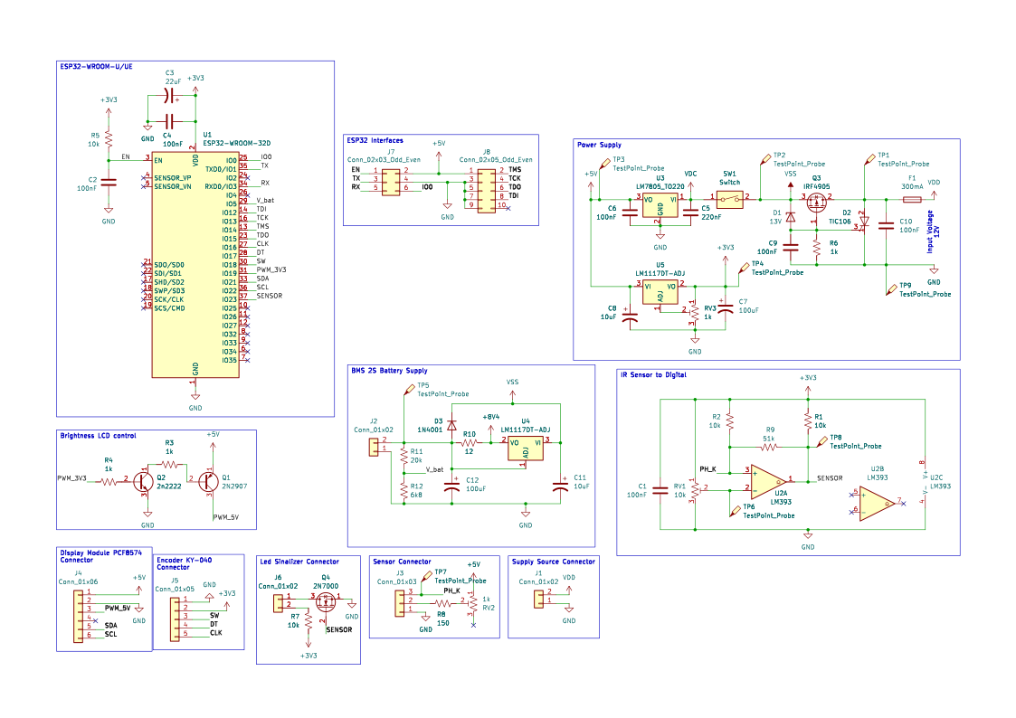
Complete Schematic
The complete schematic shows how the ESP32, power rails, sensor conditioning, user interface, and programming interfaces are connected in the same KiCad project.
Interactive BOM
 Interactive Bill of Materials
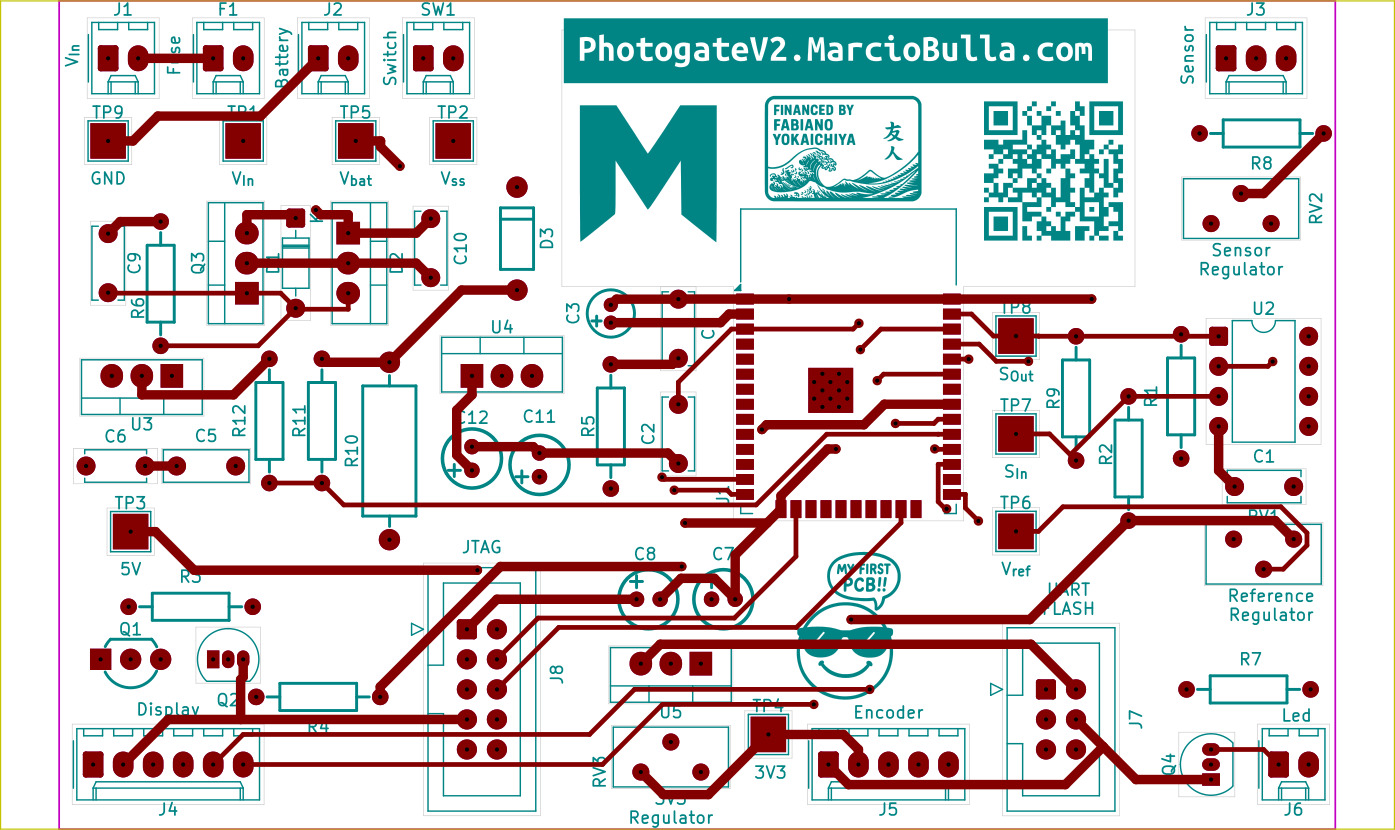
PCB Layout
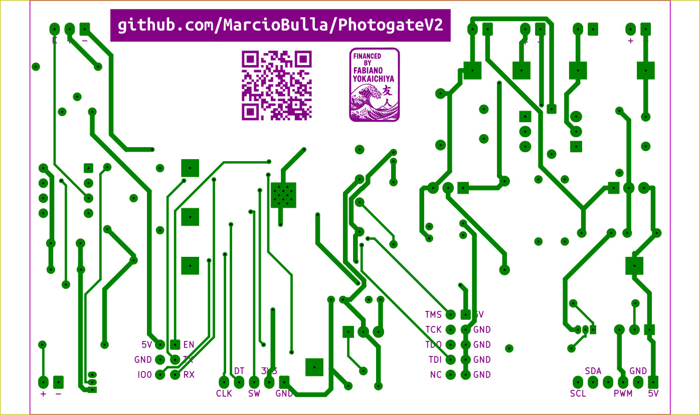
The PCB layout prioritizes through-hole components, clear labels, polarized connectors, test points, and a compact two-layer board. These images document the board design before fabrication.
Prototype Board
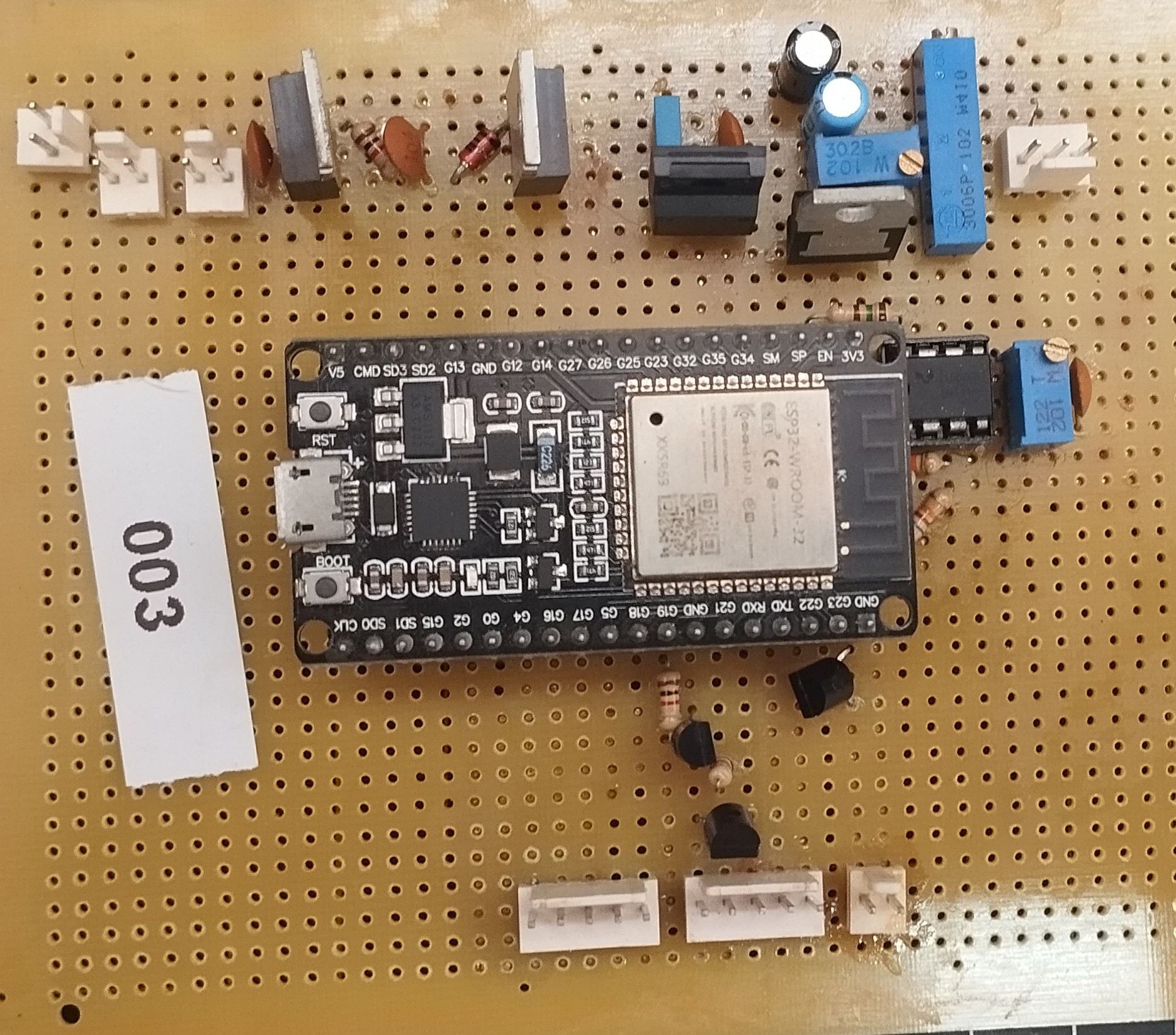
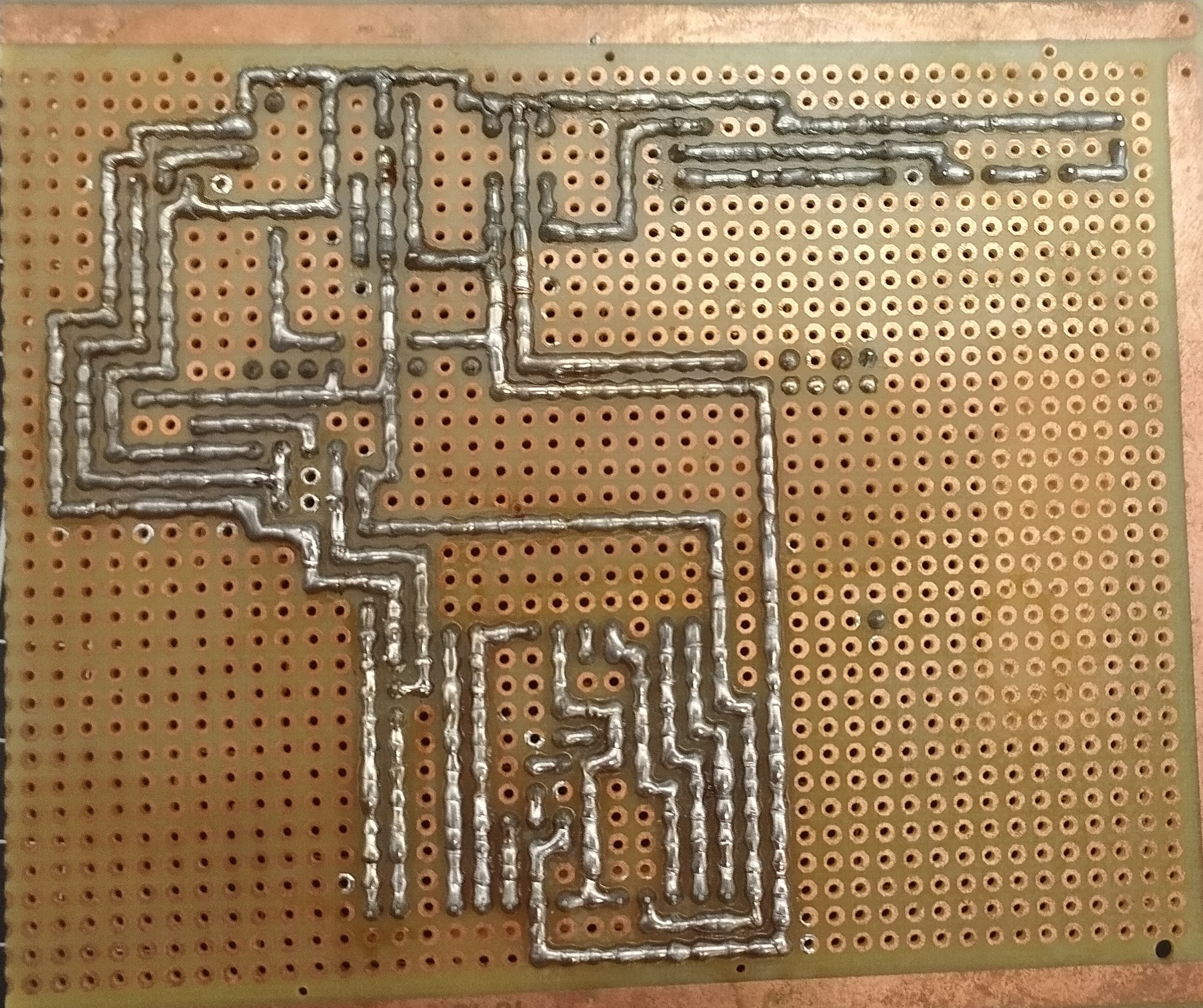
The prototype photos document the assembled hardware used during development and testing.